This is 4 channel DC digital voltmeter. In normal multimeter you can check one volt at a time but in this voltmeter you can check four different volt at a time. Also design cashing with PVC pipe for professional looking. This is very easy to make, just follow all the step in the video and make your own 4 channel voltmeter.
Components:
1) Banana Jack Plug Connector & Socket 4mm Male +Female : https://roboman.in/kmrk
2) LCD2004 Parallel LCD Display : https://roboman.in/19uy
3) TP-4056 Module : https://roboman.in/oa0m
4) Arduino Nano: https://roboman.in/59h4
5) Arduino Nano Type C : https://roboman.in/xkfu
6) MT-3608 Boost module : https://roboman.in/xdcw
7) 100K resistor: https://roboman.in/9h3u
8) 10K resistor: https://roboman.in/e3xw
9) SPST Switch : https://roboman.in/74he
10) 18650 Lithium Battery 2500mah 3C :https://roboman.in/utwc
10) 18650 Lithium Battery 2600mah 3C :https://roboman.in/mmab
10) 18650 Lithium Battery 2200mah 1C :https://roboman.in/70b5
10) 18650 Lithium Battery 2000mah 1C :https://roboman.in/7em9
10) 18650 Lithium Battery 1800mah 1C :https://roboman.in/ywss
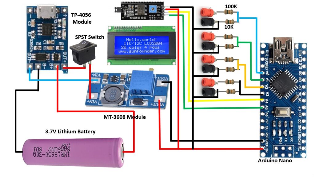
Diagram :
Code :
#include "Wire.h"
#include "LiquidCrystal_I2C.h" // library for I@C interface

LiquidCrystal_I2C lcd(0x27, 20, 4);
int analogInput = A0;
int analogInput1 = A1;
int analogInput2 = A2;
int analogInput3 = A3;
float Vout = 0.00;
float Vout1 = 0.00;
float Vout2 = 0.00;
float Vout3 = 0.00;
float Vin,Vin1,Vin2,Vin3  = 0.00;
float R1 = 99500.00; // resistance of R1 (100K)
float R2 = 10000.00; // resistance of R2 (10K)
float R3 = 98200.00; // resistance of R1 (100K)
float R4 = 10000.00; // resistance of R2 (10K)
float R5 = 98100.00; // resistance of R1 (100K)
float R6 = 10000.00; // resistance of R2 (10K)
float R7 = 100500.00; // resistance of R1 (100K)
float R8 = 10000.00; // resistance of R2 (10K)
int val,val1,val2,val3 = 0;
void setup(){
lcd.begin(20, 4);
    lcd.backlight();

   pinMode(analogInput, INPUT); //assigning the input port
   pinMode(analogInput1, INPUT); //assigning the input port
   pinMode(analogInput2, INPUT); //assigning the input port
   pinMode(analogInput3, INPUT); //assigning the input port
   Serial.begin(9600); //BaudRate
   lcd.setCursor(2,0);
   lcd.print("4 CHANNEL DIGITAL ");
lcd.setCursor(6,1);
   lcd.print("VOLTMETER");
   lcd.setCursor(6,3);
   lcd.print("LOADING....");
   delay(5000);
   lcd.clear();
}
void loop(){
   lcd.clear();
   val = analogRead(analogInput);//reads the analog input
   Vout = (val * 5.00) / 1024.00; // formula for calculating voltage out i.e. V+, here 5.00
   Vin = Vout / (R2/(R1+R2)); // formula for calculating voltage in i.e. GND

     val1 = analogRead(analogInput1);//reads the analog input
   Vout1 = (val1 * 5.00) / 1024.00; // formula for calculating voltage out i.e. V+, here 5.00
   Vin1 = Vout1 / (R4/(R3+R4)); // formula for calculating voltage in i.e. GND

    val2 = analogRead(analogInput2);//reads the analog input
   Vout2 = (val2 * 5.00) / 1024.00; // formula for calculating voltage out i.e. V+, here 5.00
   Vin2 = Vout2 / (R6/(R5+R6)); // formula for calculating voltage in i.e. GND

     val3 = analogRead(analogInput3);//reads the analog input
   Vout3 = (val3 * 5.00) / 1024.00; // formula for calculating voltage out i.e. V+, here 5.00
   Vin3 = Vout3 / (R8/(R7+R8)); // formula for calculating voltage in i.e. GND

   if (Vin<0.09)//condition
   {
     Vin=0.00;//statement to quash undesired reading !
  }
    if (Vin1<0.09)//condition
   {
     Vin1=0.00;//statement to quash undesired reading !
  }
    if (Vin2<0.09)//condition
   {
     Vin2=0.00;//statement to quash undesired reading !
  }
    if (Vin3<0.09)//condition
   {
     Vin3=0.00;//statement to quash undesired reading !
  }
Serial.print("\t Voltage of the given source = ");
lcd.setCursor(0,0);
lcd.print("VOLTMETER 1 ");
Serial.println(Vin);
lcd.print(Vin);
lcd.print("V");
Serial.print("\t Voltage of the given source 2 = ");

lcd.setCursor(0,1);
lcd.print("VOLTMETER 2 ");
Serial.println(Vin1);
lcd.print(Vin1);
lcd.print("V");

lcd.setCursor(0,2);
lcd.print("VOLTMETER 3 ");
Serial.println(Vin2);
lcd.print(Vin2);
lcd.print("V");

lcd.setCursor(0,3);
lcd.print("VOLTMETER 4 ");
Serial.println(Vin3);
lcd.print(Vin3);
lcd.print("V");
delay(1000); //for maintaining the speed of the output in serial moniter
}