Amazing Idea Using RGB LED and Smartphone
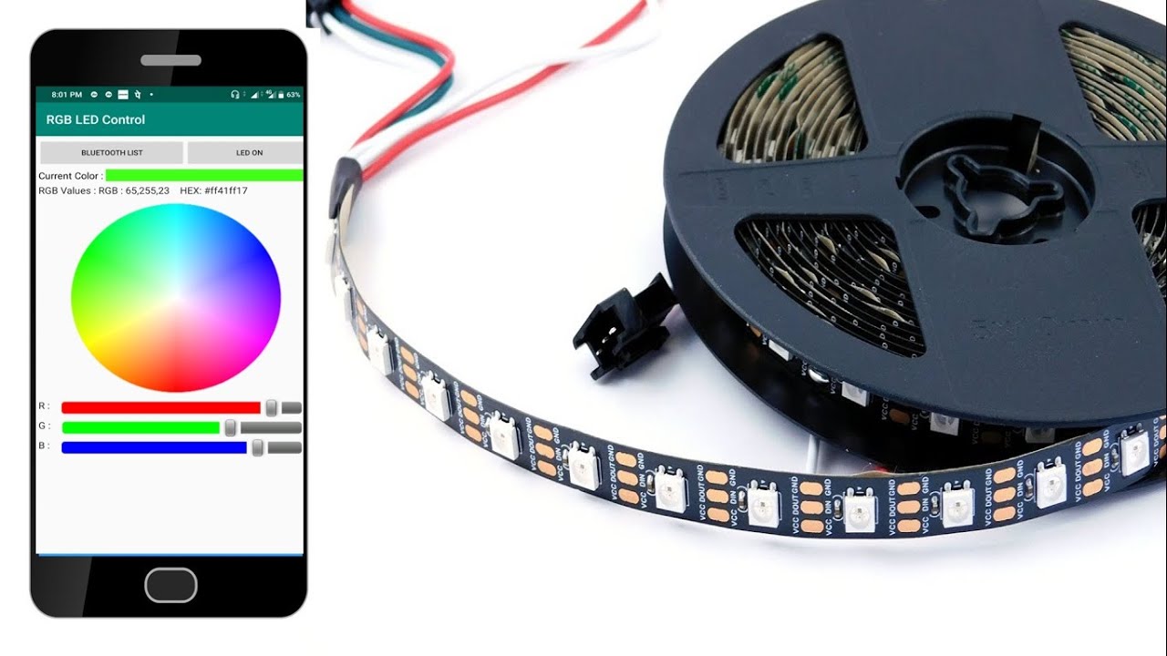
Hello friends, In this video you learn how to make RGB light control using RGB WS2812B LED. Color completely control from smartphone using Bluetooth. This is very easy to make. Its connection is very simple. Follow all the step and make your own amazing light effect for you room.
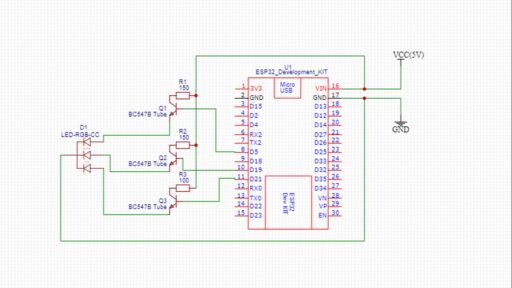
Diagram:

Code:
|
1 2 3 4 5 6 7 8 9 10 11 12 13 14 15 16 17 18 19 20 21 22 23 24 25 26 27 28 29 30 31 32 33 34 35 36 37 38 39 40 41 42 43 44 45 46 47 48 49 50 51 52 53 54 55 56 57 58 59 60 61 62 63 64 65 66 67 68 69 70 71 72 73 74 75 |
#include <SoftwareSerial.h> #include "Arduino.h" #include <Wire.h>//Include libraries: SoftwareSerial & Wire SoftwareSerial ESP_BT(0,1); //Define PIN11 & PIN12 as RX and TX pins #include <Adafruit_NeoPixel.h> #define PIN 3 // Parameter 1 = number of pixels in strip // Parameter 2 = Arduino pin number (most are valid) // Parameter 3 = pixel type flags, add together as needed: // NEO_KHZ800 800 KHz bitstream (most NeoPixel products w/WS2812 LEDs) // NEO_KHZ400 400 KHz (classic 'v1' (not v2) FLORA pixels, WS2811 drivers) // NEO_GRB Pixels are wired for GRB bitstream (most NeoPixel products) // NEO_RGB Pixels are wired for RGB bitstream (v1 FLORA pixels, not v2) // NEO_RGBW Pixels are wired for RGBW bitstream (NeoPixel RGBW products) Adafruit_NeoPixel strip = Adafruit_NeoPixel(23, PIN, NEO_GRB + NEO_KHZ800); // IMPORTANT: To reduce NeoPixel burnout risk, add 1000 uF capacitor across // pixel power leads, add 300 - 500 Ohm resistor on first pixel's data input // and minimize distance between Arduino and first pixel. Avoid connecting // on a live circuit...if you must, connect GND first. boolean RGB_Completed = false; String RGB2 ,RGB1="255.255.255"; int red=125, green=125, blue=125, starting=0; int p=0,brt=200; void setup() { Serial.begin(115200); ESP_BT.begin(9600);//#define BAUDRATE 38400 strip.begin(); strip.setBrightness(255); // colorwipemain(); strip.show(); // Initialize all pixels to 'off' } void loop() { while(ESP_BT.available()){ delay(20); char ReadChar = (char)ESP_BT.read(); Serial.println(ReadChar); if(ReadChar == ')'){ // RGB_Completed = true; break; }else{ RGB2+= ReadChar; } } if(RGB2.length()>0){ RGB1=""; RGB1=RGB2; Serial.println(RGB1); rgbcal(); RGB2=""; } if(starting==0){ rgbcal(); starting=1; } } void rgbcal(){ int SP1 = RGB1.indexOf('.'); int SP2 = RGB1.indexOf('.', SP1+1); int SP3 = RGB1.indexOf('.', SP2+1); int R = RGB1.substring(0, SP1).toInt(); int G = RGB1.substring(SP1+1, SP2).toInt(); int B = RGB1.substring(SP2+1, SP3).toInt(); for(int i=0; i<strip.numPixels(); i++) { // For each pixel in strip... strip.setPixelColor(i, strip.Color(R,G,B)); // Set pixel's color (in RAM) if(!ESP_BT.available()){ strip.show(); }else{ break; } } |


why are 2 difarent code ?