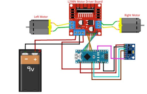
#include <PID_v1.h>
#include <LMotorController.h>
#include "I2Cdev.h"
#include "MPU6050_6Axis_MotionApps20.h"
#if I2CDEV_IMPLEMENTATION == I2CDEV_ARDUINO_WIRE
#include "Wire.h"
#endif
#define MIN_ABS_SPEED 30
MPU6050 mpu;
// MPU control/status vars
bool dmpReady = false; // set true if DMP init was successful
uint8_t mpuIntStatus; // holds actual interrupt status byte from MPU
uint8_t devStatus; // return status after each device operation (0 = success, !0 = error)
uint16_t packetSize; // expected DMP packet size (default is 42 bytes)
uint16_t fifoCount; // count of all bytes currently in FIFO
uint8_t fifoBuffer[64]; // FIFO storage buffer
// orientation/motion vars
Quaternion q; // [w, x, y, z] quaternion container
VectorFloat gravity; // [x, y, z] gravity vector
float ypr[3]; // [yaw, pitch, roll] yaw/pitch/roll container and gravity vector
//PID
double originalSetpoint = 174.50;
double setpoint = originalSetpoint;
double movingAngleOffset = 0.3;
double input, output;
//adjust these values to fit your own design
double Kp = 40;
double Kd = 1.6 ;
double Ki = 140;
PID pid(&input, &output, &setpoint, Kp, Ki, Kd, DIRECT);
double motorSpeedFactorLeft = 0.6;
double motorSpeedFactorRight = 0.6;
//MOTOR CONTROLLER
int ENA = 5;
int IN1 = 6;
int IN2 = 7;
int IN3 = 9;
int IN4 = 10;
int ENB = 8;
LMotorController motorController(ENA, IN1, IN2, ENB, IN3, IN4, motorSpeedFactorLeft, motorSpeedFactorRight);
volatile bool mpuInterrupt = false; // indicates whether MPU interrupt pin has gone high
void dmpDataReady()
{
mpuInterrupt = true;
}
void setup()
{
// join I2C bus (I2Cdev library doesn't do this automatically)
#if I2CDEV_IMPLEMENTATION == I2CDEV_ARDUINO_WIRE
Wire.begin();
TWBR = 24; // 400kHz I2C clock (200kHz if CPU is 8MHz)
#elif I2CDEV_IMPLEMENTATION == I2CDEV_BUILTIN_FASTWIRE
Fastwire::setup(400, true);
#endif
mpu.initialize();
devStatus = mpu.dmpInitialize();
// supply your own gyro offsets here, scaled for min sensitivity
mpu.setXGyroOffset(220);
mpu.setYGyroOffset(76);
mpu.setZGyroOffset(-85);
mpu.setZAccelOffset(1788); // 1688 factory default for my test chip
// make sure it worked (returns 0 if so)
if (devStatus == 0)
{
// turn on the DMP, now that it's ready
mpu.setDMPEnabled(true);
// enable Arduino interrupt detection
attachInterrupt(0, dmpDataReady, RISING);
mpuIntStatus = mpu.getIntStatus();
// set our DMP Ready flag so the main loop() function knows it's okay to use it
dmpReady = true;
// get expected DMP packet size for later comparison
packetSize = mpu.dmpGetFIFOPacketSize();
//setup PID
pid.SetMode(AUTOMATIC);
pid.SetSampleTime(10);
pid.SetOutputLimits(-255, 255);
}
else
{
// ERROR!
// 1 = initial memory load failed
// 2 = DMP configuration updates failed
// (if it's going to break, usually the code will be 1)
Serial.print(F("DMP Initialization failed (code "));
Serial.print(devStatus);
Serial.println(F(")"));
}
}
void loop()
{
// if programming failed, don't try to do anything
if (!dmpReady) return;
// wait for MPU interrupt or extra packet(s) available
while (!mpuInterrupt && fifoCount < packetSize)
{
//no mpu data - performing PID calculations and output to motors
pid.Compute();
motorController.move(output, MIN_ABS_SPEED);
}
// reset interrupt flag and get INT_STATUS byte
mpuInterrupt = false;
mpuIntStatus = mpu.getIntStatus();
// get current FIFO count
fifoCount = mpu.getFIFOCount();
// check for overflow (this should never happen unless our code is too inefficient)
if ((mpuIntStatus & 0x10) || fifoCount == 1024)
{
// reset so we can continue cleanly
mpu.resetFIFO();
Serial.println(F("FIFO overflow!"));
// otherwise, check for DMP data ready interrupt (this should happen frequently)
}
else if (mpuIntStatus & 0x02)
{
// wait for correct available data length, should be a VERY short wait
while (fifoCount < packetSize) fifoCount = mpu.getFIFOCount();
// read a packet from FIFO
mpu.getFIFOBytes(fifoBuffer, packetSize);
// track FIFO count here in case there is > 1 packet available
// (this lets us immediately read more without waiting for an interrupt)
fifoCount -= packetSize;
mpu.dmpGetQuaternion(&q, fifoBuffer);
mpu.dmpGetGravity(&gravity, &q);
mpu.dmpGetYawPitchRoll(ypr, &q, &gravity);
input = ypr[1] * 180/M_PI + 180;
}
}


